CRACK INDUCER PIPES
Singular continued concreting of reinforced concrete walls and walls of water tanks at long sections, however, requires certain knowledge of the properties of concrete and later rheologic influence on the behaviour of the entire structure.
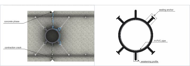
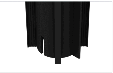
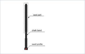
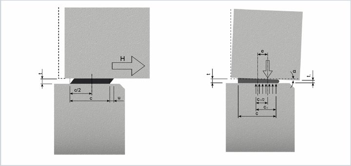
In terms of structure tightness, however, very important are additional concrete deformations that take place during the use of the structure, occurring due to concrete contraction and creep. In order to limit the emergence of uncontrolled fractures and the costly and time-consuming repair work occurring because of this, controlled crack inducer pipes should be used. Their two-stage behaviour weakens, in a controlled manner, the wall cross-section, causing vertical cracks along the weakening profile, and ensures tightness by virtue of sealing anchors.
GENERAL INFORMATION
General information
Singular continued concreting of reinforced concrete walls and walls of water tanks at long sections, however, requires certain knowledge of the properties of concrete and later rheologic influence on the behaviour of the entire structure. In terms of structure tightness, however, very important are additional concrete deformations that take place during the use of the structure, occurring due to concrete contraction and creep.
By virtue of complexity of rheologic effects and complicated mathematical procedures, as well as numerous assumptions of the threshold state to be made during the calculation of these parameters, they are often neglected in terms of strength calculations for structures. In such cases, the designer’s role is often limited to including maximum expansion joint spacings in the design, indicating the minimum reinforcement field and the guidelines to be fulfilled with respect to concrete layout and care.
Engineering practice shows, however, that such means are not always sufficient. The result is wearing of shields. The difficulty of achieving good seals, and sometimes of indicating of the proper leak spots, the emerged cracks, may reduce the usability of a structure and greatly increase its usage costs. From the practical standpoint, the following is worth quoting:
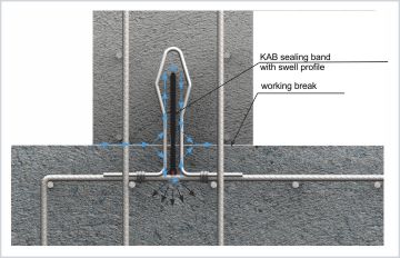
‘Prevention is better than cure’ with respect to repair of cracked shields. Seeking to limit uncontrolled reinforced concrete wall fractures, one available solution is weakening of the wall cross-section through creation of precisely positioned vertical cracks. The use of Besaflex type S induced crack piping additionally protects the created crack from penetration by pressing water using the labyrinth effect.
| Properties | Unit | Requirements | Tested per |
| External form | – | No cracks, rifts | Visual evaluation |
| Shore hardness | ˚Sh | 83±5 | PN-EN ISO 868:2005 |
| Stretch resistance | MPa | ≥ 9 | PN-EN ISO 527-2:1998 |
| Relative elongation at break | % | ≥ 200 | PN-EN ISO 527-2:1998 |
| Shear resistance | N/mm | ≥ 8 | PN- ISO 34-1:2007 |
| Low temperature behaviour, -20 ˚C, relative elongation at break | % | ≥100 | PN-EN ISO 527-2:1998 |
| Controlled crack inducer pipe | ||||||||
| Symbol | a [mm] | d [mm] | f [mm] | Wall width [mm] | Package [pcs./pallete] | Sales unit | Weight [kg/mb] | Art. no. |
| Type H1 L=3 m | 128 | 88 | 25 | 240÷350 | 100 | pcs. = 3m | 2,80 | SU-TU-RR-0-02357 |
| Type H1 L=4 m | pcs. = 4m | SU-TU-RR-0-02358 | ||||||
| Type H1 L=5 m | pcs. = 5m | SU-TU-RR-0-02359 | ||||||
| Type H2 L=3 m | 235 | 175 | 25 | 350÷500 | 50 | pcs. = 3m | 5,50 | SU-TU-RR-0-02360 |
| Type H2 L=4 m | pcs. = 4m | SU-TU-RR-0-02361 | ||||||
| Type H2 L=5 m | pcs. = 5m | SU-TU-RR-0-02362 | ||||||
| Type H2 L=7 m | pcs. = 7m | SU-TU-RR-0-02363 | ||||||
| Type H3 L=3 m | 110 | 60 | 25 | 170÷240 | 120 | pcs. = 3m | 2,00 | SU-TU-RR-0-02364 |
| Type H3 L=4 m | pcs. = 4m | SU-TU-RR-0-02365 | ||||||
| Type H3 L=5 m | pcs. = 5m | SU-TU-RR-0-02366 | ||||||

Usage
Hidroplasto controlled induced crack pipes should be used at sites under threat of influence of liquids under hydrostatic pressure or of groundwater, for which the formwork or concreting technology requires the works to be carried out along large wall sections. The induced crack pipe selection depends on the thickness and height of the component to be weakened. No joined pipes should be used, and no piping composed of short sections should be used either. The axial separation of the selected controlled induced crack pipes depends on the following formula:
where:
R – axial pipe spacing,
h – height of component to be weakened,
g – component thickness.
INSTALLATION
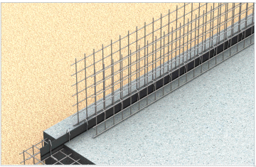
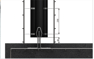
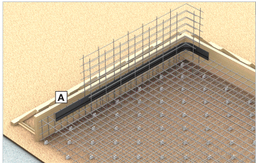
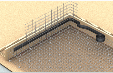
The cut should be executed perpendicular to the smooth weakening profile niches, with a length allowing embedding of the pipe on a band at a height of 5 cm above the slab face. The induced crack pipe and the external reinforcement arrangement are best trimmed to size directly at the construction site. All works related to the placement of the pipe at the target location are best done before execution of the horizontal wall reinforcement bars and arrangement of the formwork hindering access and the installation specialist’s range of motion.
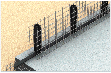
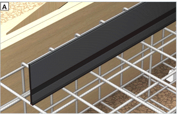
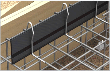
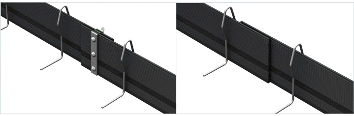
The controlled induced crack pipe should be embedded in a stable manner on the internal day joint band or the sealing sheet steel. At the same time, sealing anchors should be tied to the wall beginning bars using installation grips and tie wire, utilising at least 8 pcs./running metre.
During concreting works, make sure that the height of the laid out concrete mix is equal on both sides of the pipe. After the pipes are concreted up to the desired height, the interiors of the induced crack pipes must also be filled. The pipe placed for rigidity must not be removed.
 |  |
| Step 1. Concreting of the sealing band at the slab-wall intersection | Step 2. Cutting of the pipe underside and trimming to size. |
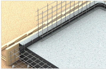
 |  |
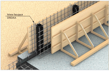
| Step 3. Embedding pipes on the sealing band and mounting to reinforcement bars. | |
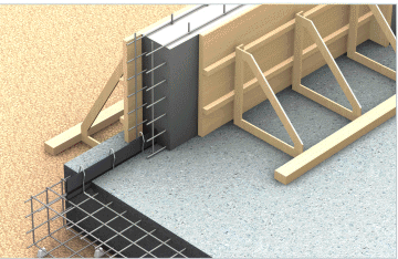
 | 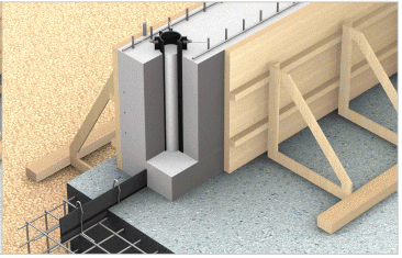 |
| Step 4. Embedding edge beams and arranging the formwork. | Step 5. Wall concreting. |
Concreting phases
 |  |
| Step 1. Wall formwork set-up. | Step 2. Concreting of the lower part of the entire wall. |
 |  |
| Step 3. Concreting the wall to its designated height. | Step 4. Concreting of the controlled induced crack pipe interior. |
CONTROLLED CRACK INDUCER PIPES


 A modern, stable and universal use spacer made of synthetic material, with a length of 2000 mm. Allows achieving cover thickness values between 15 mm and 50 mm, side recesses reduce thermal expansion and allow the reinforcement bars and the spacer itself to be fully covered.
 Its advantage is the option of arranging it on a soft surface, i. e. styrofoam, mineral wool, bentonite or a binding layer. Spacer length: 2000 mm.
 Stable linear spacing component for lower reinforcement layer, with a length of 2000 mm. Numerous openings allow proper coverage by concrete both of the rebar as well as the spacer. Thanks to this, such flaws as linear cracks where the reinforcement concrete component deflects.
 Synthetic material linear spacer for the lower horizontal reinforcement bar layer, utilised mainly in pre-casting plants. It is characterised by a small footprint, thanks to which it has limited visibility in the concrete on the non-processed surface. Specially shaped endings allow joining of the spacers in order to increase their joint length. Usable length per segment is 485 mm.
 Synthetic material spacer for lower layers of horizontal or vertical reinforcement bars, utilised mainly in pre-casting plants. It has limited visibility on non-processed surfaces. It has clamps helping to maintain the rebar at its designated spot. Spacing between clamps is 150 mm, total length 283 mm, width 48 mm.
 Synthetic material linear spacer for the lower horizontal reinforcement bar layer, utilised mainly in pre-casting plants. It is characterised by a small footprint, it has limited visibility in structural concrete on non-processed surfaces. Specially shaped endings allow joining of the spacers in order to increase their joint length. Usable length per segment is 95 mm, lenght 215 mm.
 Spacer for horizontal rebar, mainly used at precasting plants. It is characterised by a small footprint, which causes it to be invisible in unprocessed external concrete components. Circle diameters between 180 mm and 315 mm.
 PADIX – injection spacer characterised by enhanced resistance. Recommended for use for vertical rebar.
 Spacer foreseen for reinforcement bars laid out on a soft layer, i. e. styrofoam, mineral wool, bentonite matt or directly on the soil. Depending on the layout of the rebar on the spacer, two cover thickness values may be attained.
 Spacer with a special clamp. Maintains stability and binds well with concrete.
 Spacer used for horizontal reinforcement systems. Equipped with clamps protecting the spacer against shifting.
 Spacer for horizontal reinforcement bars. Allows for five different concrete cover thickness values of 15 mm, 20 mm, 25 mm, 30 mm and 35 mm depending on the spacer type, its mode of layout on the surface and the specific layout of reinforcement bars.